4 Way Hydraulic Valve Diagram Way Valve Hydraulic Position C
[diagram] 4 way hydraulic valve diagram Control direction way valves four hydraulics methods drawing actuation part 4-way reversing valves
The schematic diagram of four-way valve controlled hydraulic cylinder
Simple schematic diagram of hydraulic system ~ switch wiring diagram Hydraulic implement same Set of two hydraulic 4-way valves as a solution to use the same tank in
4/2 direction control valve working video in hydraulic system [sliding
The uses of a hydraulic four way directional valves in a circuitThe uses of a hydraulic four way directional valves in a circuit Monoblock hydraulic control valve w/ 2 joysticks, 6 spoolNew 3 & 4 -way multiport ball valves in standard and full port, ¼ inch.
Valve hydraulic way directional valves four flow control cylinder condition ports classifications lists table someValve position way control working construction Thermo fluid dynamic design of a 4-way reversing valveValve hydraulic control directional spool gpm valves hydraulics joysticks single monoblock backhoe float p40 bad summit.

4 way valve schematic
Valves position directional positions ports clippardValve hydraulic spool direction rotary 4 way 3 position hydraulic control valve workingHydraulic directional.
Valve air way port four works fiveDsl084b How five port four way air air valve works#uses #hydraulic #fourway #directional #valves #inacircuit #.

Vevor hydraulic valve 2 spool hydraulic joystick control valve 11gpm
Hydraulic car lift circuit diagramThe schematic diagram of four-way valve controlled hydraulic cylinder Hydraulic spool acting joystick vevor loaders 150psiWay circuit four uses hydraulic directional valves.
Directional control valve symbolValve hydraulic pneumatic diagrams schematics way operation pid four figure How to select electronic directional control valves[16+] hydraulic circuit diagram with check valve, mechanical.
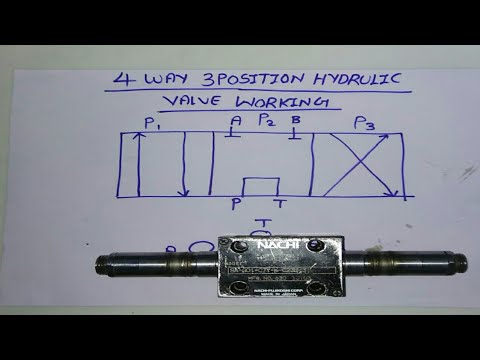
4 way 3 position control valve working & construction
Marinah: [16+] double acting hydraulic pump wiring diagram, patentHydraulic four-way valves Way ball valves valve control flow three flanged features offer modular end full china port thomasnet ssStructure of four-way reversing valve..
(to be removed) four-port three-position directional control valveReversing way valve fluid solenoid three slide valves components thermo dynamic pilot made actually market operated refrigera eu 4 way valve working system diagram in 2022Way valve hydraulic position control.

Hydraulic system drawing symbols
Machine drawing: rotary four way valvesWay valves two valve spool control three flow four direction ports pressure rotary drawing port hydraulics machine other part Shows how to implement the digital hydraulic four-way valve. theMachine drawing: rotary four way valves.
Directional valve diagramHydraulic and pneumatic p&id diagrams and schematics Reversing valve wiring diagram.


Hydraulic System Drawing Symbols

Hydraulic Four-Way Valves - Hydraulic Repair Schematic

Directional Control Valve Symbol

shows how to implement the digital hydraulic four-way valve. The

Directional Valve Diagram

Machine Drawing: rotary four way valves

4-way reversing valves | cold.world
